
Mercedosaurus Rex at Indianapolic Park
Part 9: Pre-May '94 plans
Author
- Henri Greuter
Date
- December 4, 2009
Related articles
- March-Alfa Romeo 90CA - Fiasco Italo-Brittanico, by Henri Greuter
- March-Porsche 90P - The last oddball at the Indianapolis Motor Speedway, by Henri Greuter
- Penske-Mercedes PC23-500I - Mercedosaurus Rex at Indianapolic Park, by Henri Greuter
- Introduction
- Part 1: Penske Racing at Indianapolis - new standards
- Part 2: Ilmor Engineering at Indianapolis
- Part 3: Mercedes, Benz and Mercedes-Benz at Indianapolis up until 1993
- Part 4: Equivalency formulas - waiting for things to go wrong
- Part 5: Stock blocks - keeping them rolling and promoting 'Born in the USA' technology
- Part 6: Indianapolis 1991 - Chevy And Rich Team owners
- Part 7: The Speedway narrowed, its speeds lowered
- Part 8: The forerunner
- Part 10: Penske PC23 - a home for the engine
- Part 11: The 1994 Indycar season until mid-April
- Part 12: The unfair advantage and when others have it
- Part 13: Practice during the 1994 'Month of May'
- Part 14: Other bespoke-design 209s
- Part 15: From the last weekend of May '94 to the end of the season
- Part 16: Could the Mercedes Benz 500I have been stopped in time?
- Part 17: Creating an extinct species without it being forbidden, initially at least
- Part 18: The 1995 '500' - Did the Mercedosaurus bite its masters after all?
- Part 19: A possible twist of fate for Rahal-Hogan and Penske as a legacy of the 500I
- Part 20: Re-evaluation of our verdict
- Part 21: PC23's further active career after 1994
- Part 22: USACs points of views and some answers
- Part 23: The loose ends that didnt fit in anywhere else and the epilogue
- Part 24: "Plan your work; work your plan" - Chuck Sprague on the PC23
- Appendix 1: Specifications
- Appendix 2: Car and driver appearances and performances during the Month of May 1994
- Appendix 3: Chassis, entry, practice and race numbers in 1994
- Appendix 4: PC23's 1994 results sans Mercedes Benz 500I
- Appendix 5: PC23's 1995-'96 results sans Mercedes Benz 500I
- Appendix 6: A reflection on the PC23 chassis used by Team Penske in 1994
- Appendix 7: A review of Beast by Jade Gurss
What?Ilmor '265E' V8 (side view) When?late 1993 |
 |
Why?
The CART teams safely hung on to the use of quadcam 2.65-litre V8 engines at Indy, the same they could use for the remaining CART events. Still, already in 1992 and 1993 there was some talking about who was to build a pushrod V8 from scratch. Nevertheless, no such engine was built yet. Only Peter Greenfield and his little company were known to be working on such an engine for some time already although it didn't appear in public yet. But this underfunded enterprise needed its time.
Mario Illien, one of the two directors of Ilmor Engineering had no reasons to complain. Ever since '88, his engines had won six straight 500-miles races at Indy (88-92 with the original first design, the Ilmor 265A, 93 with the 265C). Nevertheless, he feared the idea of an opponent building a clean-sheet-of-paper pushrod V8 and preferred to build one himself. Ilmor was partly funded by General Motors and as a result the Ilmor engines were named Chevrolet. GM wasn't very keen on having Ilmor build another engine to dominate at Indianapolis. Despite Chevrolet's success of the past years, the initially limited availability of the 265A in recent years had generated some bad publicity and negative feelings towards Chevrolet among race fans. Besides that, GM reckoned that within their own organisation enough knowledge about how to built a pushrod racing engine was available. There was, for example, the famous small-block Chevy V8, used in so many varieties of American racing. But did it make sense to start with a nearly 40-year-old basic design with at least 5-litre capacity and then reduce its capacity to less than 3.5 litre, especially since by now the trend was to design new engines as small and compact as possible?
Even so, somewhere within the GM organisation, people were indeed working on a pushrod racing engine. By 1993, however, the relationship between Ilmor and GM began to fall apart slightly. At the same time, Ilmor began to flirt with some German car builders in order to study the possibilities of joining them in order to run and finance the Ilmor V10 Formula 1 engines. Among those companies was Mercedes-Benz. But another shareholder within Ilmor got ever increasing contacts with Mercedes Benz. His name: Roger Penske.
Karl Ludvigsen wrote in his book Prime movers that the very first conversation between Roger Penske and Paul Morgan in which a pushrod engine had been discussed had taken place in 1983 when a Buick-powered car came into their view. Penske had referred to the engine as a manner to win the pole but that it would take a fortune to develop it. But Morgan believed it would not be that bad. This story can't have been entirely correct since there were no Buicks at the Speedway yet that year, other than the pace car and other ceremonial cars. Had it taken place in 1983, then it must have been when the two men saw a turbocharged Chevy V6-powered car of which a few were entered. If it was indeed a Buick V6 that inspired the conversation, then the earliest it could have happened is one year later in 1984 since that was the debut year of Buick at Indianapolis.
In the years that followed, Penske had little reason to consider Buick or any other turbocharged stock block for his cars. As part owner of Ilmor he had access to the Ilmor-Chevy. And once that engine had finally been cured of its initial fragility there was no need to look for anything else anymore. This changed however in 1992.
A little-known fact about Penske Racing´s planning for the future was that already in 1992 there had been talk about building a pushrod. The 1992 '500' had become a fiasco for Penske and right after the race the team held a meeting in one of the garages within Gasoline Alley to discuss what had gone wrong. One of the things that had been noticed by the team was the outrageous speeds of the fastest Buicks, supporting the potential of the stock-block V6 with its higher turbo boost and larger capacity. Mario Illien, also present at that meeting, then suggested that Ilmor could build a purpose-designed pushrod engine. Despite a lot of interest by Roger Penske for this idea, nothing happened with it in time to have such an engine in 1993.
In late May 1993 Ilmor and Penske made up the plans for 1994, one of those being the development of a new quadcam: the 265D. Illien then suggested to Penske that Ilmor design and build a pushrod V8 for Indy. Illien feared the results for his engines if another engine builder would come up with a purpose-design pushrod V8 and in order to counteract such an attack, he wanted to have one built by Ilmor. So he did some homework and suggested to Roger Penske that Ilmor had to build a pushrod. When Penske asked what kind of power such an engine could provide, Illien told him it was to be about 940hp.
Once it became obvious to Roger Penske that such an engine would have a power advantage of 150hp or more he became highly interested in the project, especially since the modified corners had made the straights more important than ever as the place to overtake. However, that would mean building two entirely different cars for the '94 season, something that was even beyond the financial capacities of Team Penske, so when Mario Illien promised to build Penske a pushrod V8 that was exactly the same length as the new-for-1994 quadcam (thus making it possible to change the type of engine within the very same chassis) he got the green light to go ahead with a secret project that was to shock the racing world.
Concept philosophy
The Buick production-derived engines had produced promising power outputs but their background brought some handicaps. Of course, every improvement possible on the engine was done, no matter if that meant adopting racing engine technology. For example: the 1985 Buicks that had won the first two starting positions had been fitted with oil pumps taken from Cosworths. According to Buick, it had been one such oil pump that had failed on the pole-winning car of Pancho Carter who had finished 33rd as a result.
Still, the V6 had some setbacks. Among them was a limited useful rev range. They didn't turn the RPMs like the quadcam racing engines did. This required modifications on the gearbox and final drive ratio. The complicated valve train with all its different components between camshaft and valve was a major restriction in the ability of the engine to turn high revs. And since only two valves were allowed, these valves had to be as big as possible to enhance gas flow in and out of the cylinders. Larger valves however weighed more and that was another factor that restricted the RPM speeds.
But also, having bigger (heavier) pistons was another factor. Increasing the number of cylinders to the maximum allowed eight allowed a narrower bore, thus reducing piston mass. When the stroke was reduced as well, that enabled the use of slightly smaller connecting rods as well as slightly smaller, hence lighter pushrod components. This enabled higher RPMs than a V6 of similar capacity could make. And of course it offered the advantage of a larger piston area.
One thing however remained in favour of retaining an as large as possible bore: it enabled the use of larger valves, thus enhancing the breathing capacities another time.
Despite all the things done to enable more revs, one very important factor remained which made it impossible for Illien to create an extreme short stroke engine (thus wide bore) that could rev happily way over 10000 rpm. Because of the larger capacity for each individual cylinder, both bore and stroke were larger than those for the 1994 quadcam engine, but the bore could not be too large because the entire length of the engine had to remain identical to that of the quadcam. Some of the length of the quadcam 265D came from the location of the gears to drive the camshafts. This was not necessary on the pushrod and that was the additional length available to widen the bore.
In theory, because of the reduced stroke compared with that of a V6, the entire block could become lower which benefited aerodynamics and the center of gravity. Thus with a clean sheet of paper to start the design, it was not strange that Illien went for a V8 engine and also tried to optimise whatever could be optimized within the design. There was to be no modifying an existing design and still end up with a compromise. A pushrod type engine meant compromises, they were inherent to the concept. But with respect to some of those compromises, Illien was in the position to make his own decisions as of what and how it had to be compromised instead of being forced to accept what a production based block forced him to.
Design phase and construction
Note in advance: The pictures in this chapter were kindly provided by Tony Matthews and the copyrights belong to him. Please respect these rights and do not reproduce any of these pictures!
The entire Ilmor pushrod project was to be carried out in the biggest secrecy possible to ensure that Penske Racing would not be bothered by rivals who came up with a similar engine, and hence lose its advantage. If time was too short to get their own engine, then the opposition might try to talk USAC into a sudden rule change that could take away the advantages of the pushrod engine. One of the masterstrokes in keeping everything a secret was that the engine got the name 265E. All drawings carried this designation, thus suggesting they were related to the 1995 quadcam engine. (The 1994 engine, designed in June and July '93 was the 265D. The 265D was said to be an almost entirely newly designed engine.)
Illien, who had three assistants on the project, began the design of the pushrod engine mid July, which was his first ever non-DOHC four-valve cylinder design. To his credit, he did not merely copy a pushrod design as used in US racing like, for example, NASCAR. Although the engine was a pushrod, it wasn't anything like a hopped-up stock block, comparable with Detroit Iron. Illien's pushrod truly was a racing engine design as much as possible, but one that was compromised with the single-cam, pushrod-activated, two-valves-per-cylinder head in order to employ the maximum allowable cylinder capacity and turbo boost. But those restrictive components like the pushrods and cylinder head design were optimized as much as possible in order to provide an as smooth as possible gas flow in and out of the cylinders as well as an optimal as possible cylinder head design to provide optimal combustion. Without the use of computer design technology it would have been impossible to make the drawings of the cylinder head.
Also, fulfilling the promise of making the engine interchangeable with a 265D engine within a 1994 Penske chassis caused Illien some headaches. Apart from being identical in length, the crankshaft centerline of the /E had to be in exactly the same position as /D in order to be mated with the gearbox. The engine also had to be as wide as the 265D was. In fact, it became a bit narrower. The use of a Vee angle of 72 degrees permitted such. This was a clear example of the advantage of a purpose-design engine: not a single production pushrod V8 built anywhere had such an unusual Vee angle for a V8. Hardly any details about the engine and its specifications were released before and during 'the month of May', but extended descriptions about the engine were published later on. We will see further on in this piece how this could happen.
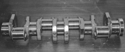
The block itself was made out of aluminium. The distance between the cylinder centers was 109 mm, it had 5 main bearings for the crankshaft. The crankshaft was a 180 degree and had four counterweights.
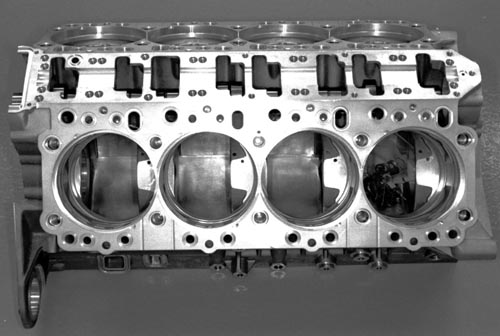
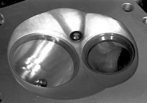
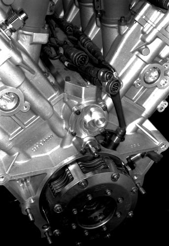
The Ilmor 265E cylinder block. (photo courtesy Tony Matthews, used with permission)
A view on the cylinder block. The cylinder liners are not installed. As can be seen, the bore of the engine was as large as the block permitted. (photo courtesy Tony Matthews, used with permission)
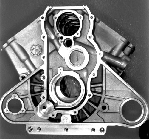
The front end of the crankcase, visible is how the camdrive tower was to be with the gears installed.
(photo courtesy Tony Matthews, used with permission)
The crankshaft seen from aside (photo courtesy Tony Matthews, used with permission)
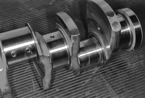
A detail picture of the crankshaft. The dark circular areas on the most right counterweight are tungsten based inserts. Since tungsten has a much higher density than steel it enabled the counterweights to be smaller for the same amount. (photo courtesy Tony Matthews, used with permission)
Although Illien and his men could have gone for a smaller bore than was used on the Buick V6 because of two more cylinders, the design team still opted for a fairly large bore.
The bore and stroke values of the engine were 97 mm and 58 mm, resulting into a bore stroke ratio of 0.6. Interestingly, this makes the /E an even more oversquare engine then the preceding 265A, 265B and 265C which all had a bore/stroke ratio of 0.62 (88 x 54.4 mm) though all these three engines revved faster than the /E ever was to do. The compression ratio was set at 11.0.
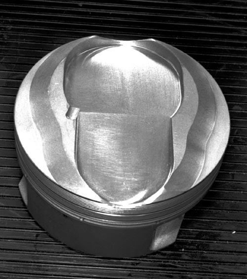
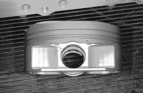
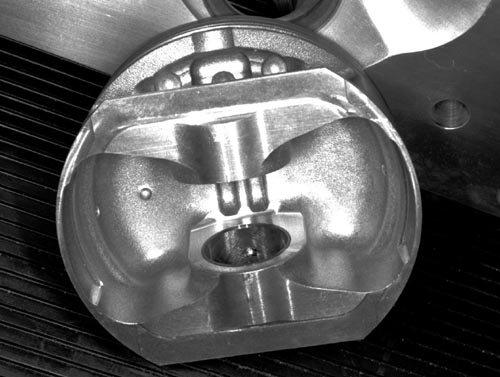
The piston of the 265E, seen from above, aside and the underside. The little indent within the surface of the top of the piston was right under the spark plug, located within the roof of the combustion chamber. (all photos courtesy Tony Matthews, used with permission)
The crankshaft and pistons were connected with 116 mm long, I profile connecting rods made of steel.
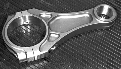
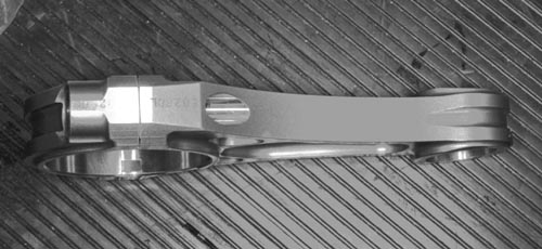
This is how the connection rod looked (photos courtesy Tony Matthews, used with permission)
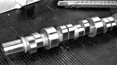
In order to make the pushrod components as small and light as possible and reduce the possibility of the rods 'flexing', the camshaft was fitted rather high within the block. This enabled the actual pushrods to be as short as possible. The camshaft itself was gear-driven and had a pendulum-type damper in the nose. The cam rotated in four caged roller bearings on 45 mm journals and a ball bearing in the front. The rear end of the cam also drove a scavenge pump for the turbocharger.
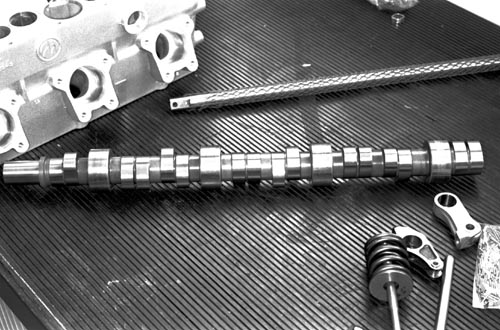
Amids some other components, this is the lone camshaft that the 265E possessed, a key component of the engine (photo courtesy Tony Matthews, used with permission)
A detail of the camshaft, giving an impression of the cam profile used.
(photo courtesy Tony Matthews, used with permission)
The pushrods were not in direct contact with the camshaft. Finger followers were in contact with the camshaft and those followers operated the pushrods. The finger followers themselves were fitted onto a shaft above the camshaft.
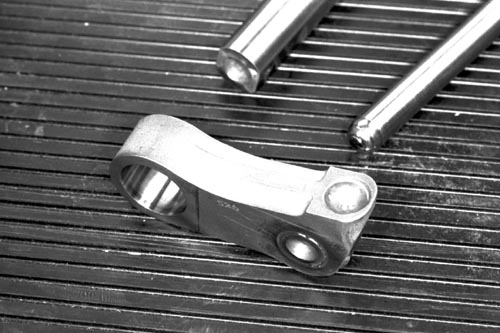
This is one of the finger followers of the cam. On the right you can see the little hole in which the pushrod rested. On the left the opening for the shaft on which the fingers were fitted.
(photo courtesy Tony Matthews, used with permission)
One advantage of the large bore dimension was the fact that it allowed larger valves to be used as well, improving the gas flow through the cylinders. The engine used an inlet valve with a diameter of 52.5 mm, the exhaust valve diameter was 39.7 mm in diameter. In particular the inlet valve was quite large and as a result, it wasn't very light, although it helped that the valves were made out of titanium.
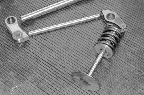
The entire pushrod system in one picture. On to the shaft on which the finger follower (on the left) was located. The pushrod activated the rocker arm that was connected with the valve.
(photo courtesy Tony Matthews, used with permission)
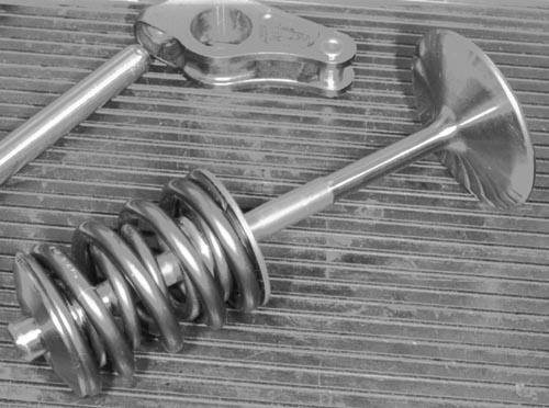
One of the valves, two hairpin springs were used. Also visible is how the pushrod activated the rocker arm.
(photo courtesy Tony Matthews, used with permission)
The underside of the rocker arm (photo courtesy Tony Matthews, used with permission)
A rocker arm installed on top of the cylinderhead. (photo courtesy Tony Matthews, used with permission)
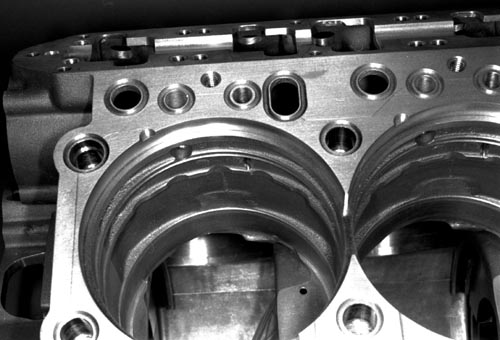
The cylinder block seen from above (photo courtesy Tony Matthews, used with permission)
Two views on the roof design of the combustion chamber. (photos courtesy Tony Matthews, used with permission)
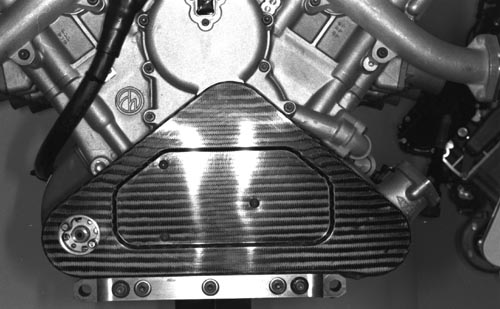
The cam cover on the engine was a stressed member and it carried the engine and suspension loads into the chassis.
Illien did use the oil pumps of the 265D on the /E. Since the /E used lower revs then the 265D, the drive ratio of the oil pumps was changed accordingly to let them turn as fast as they did on the 265D and have enough pumping capacity.
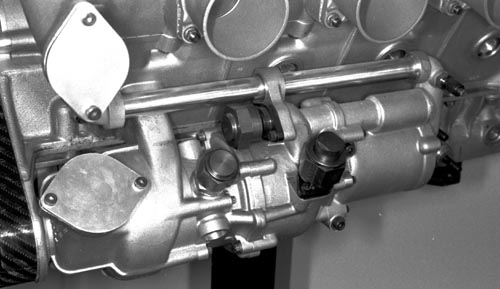
The oil pump arrangement on the 265E, seen from aside (photo courtesy Tony Matthews, used with permission)
The gear drive system of the oil pumps was neatly covered. (photo courtesy Tony Matthews, used with permission)
Illien didn't avoid less optimal options when absolutely necessary. It turned out that the V8 needed much longer inlet pipes between inlet plenum and cylinder than the 2.65 litre /D in order to obtain a flat torque curve. Illien gave his pushrod the required longer inlet tubes though it raised the overall height of the engine almost 4 inches. It raised the weight of the engine as well as its C of G and it would result in an aerodynamic disadvantage, but the increase in power could overcome most of that handicap and much more than that too .
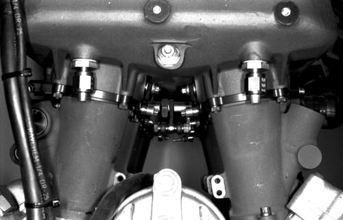
A detail photo of the long inlet tubing the 265E needed for optimal results.
(photo courtesy Tony Matthews, used with permission)
The relations between GM and Ilmor came to an end after 1993. A new partner was to become involved with Ilmor Engineering: Mercedes was to give their names to the Ilmor engines from 1995 on, but Ilmor would be out on its own during 1994. The new-for-1994 quadcam engines prominently carried Ilmor's own name on the cam covers, but a few Mercedes officials were informed about the existence of the pushrod engine.
Another decoy ploy used by Ilmor was that when drawings and parts required for the 265E caused questions it was referred to as being part of the GM pushrod. Ordering certain components was tricky but Penske Racing provided the perfect decoy for that, ordering typical pushrod engine components on behalf of Penske South's NASCAR program in which Pontiac V8s were used.
Initially, the project was bankrolled by Roger Penske. But Mario Illien was prepared should Ilmor find a new partner for the engine. The coil covers were easily removable. New versions, carrying the name of whatever company wanted to finance the project could be made with ease
The clutch on the 265E, right above it is the scavenging pump for the turbocharger, driven by the camshaft.
(photo courtesy Tony Matthews, used with permission)
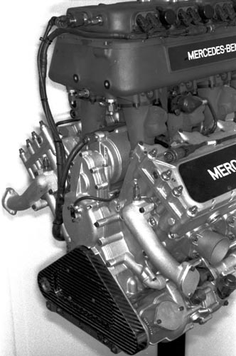
The front end of the engine (photo courtesy Tony Matthews, used with permission)
A complete engine seen straight ahead at the front side showing off how tall it was.
(photo courtesy Tony Matthews, used with permission)
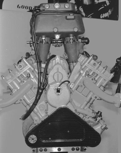
And seen from aside, the Ilmor 265E (photo courtesy Tony Matthews, used with permission)
The design and the construction of the engine caused quite a strain on the people at Ilmor. In his book Prime Movers writer Karl Ludvigsen told some very interesting stories about the kind of things that happened at the Ilmor factory. Everyone was involved somehow. If it wasn't that someone worked directly on the E engine, then he or she was doing other work that enabled someone else to do work on the E.
Curiously, one of the reasons that made Mario Illien want to built a pushrod also enabled him to carry the project out. With the arrival of Ford and Honda in CART the demand on engines to be supplied by Ilmor had reduced a bit, putting less stress on the production units at the factory, but this stress and much more came back with the /E taking up this capacity. Work on the first castings started in September 1993.
The final product had some important parameters in common with the Quadcam 265D engine. Length was identical, it was slightly smaller but significantly higher by about 4 inches (10 cm). The 265E weighed in at 123 kg, about 1 kg less than the 265D. Despite being lighter, because of being higher, the CG of the 265E was higher then that of the 265D.
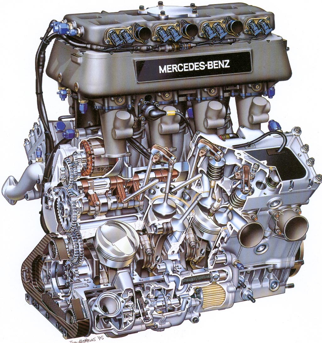
This magnificent cutaway drawing of the Ilmor 265E, made by gifted artist Tony Matthews, shows off how ingenious the valve and pushrod arrangement on this engine was. Tony made this drawing with help of a number of B&W pictures. The pictures provided for this chapter by Tony were also used to create this drawing. The drawing has found its way onto the internet but it is reproduced here, courtesy of, and with approval of Tony Matthews.
Click on the picture for a full-screen version!
For more detailed descriptions about the design and construction of the Ilmor 265E as well as its development I recommend Karl Ludvigsen's books QuickSilver Century and Prime Movers.
For inside stories about the design of the engine I recommend the book Beast by Jade Gurss.
Compared with the inspiration: the Buick V6
Listing the figures of the Ilmor 265E, and comparing them with the values of the Ilmor/D, appears to make the most sense, although effectively the Ilmor 265E was intended to be like the Buick but a lot better and without some of its handicaps. Thus it is not so strange to compare the 265E with the Buick V6 to see in which areas the Ilmor made its gains on the V6. Surprisingly, a number of dimensions are very close to another.
| Buick V6 (1992) | Ilmor 265E | Ilmor value in % of Buick value | |
| Bore | 99.0 mm | 97.0 mm | 97.9% |
| Stroke | 73.1 mm | 58.0 mm | 78.7 % |
| Bore/Stroke ratio | 0.74 | 0.6 | |
| Single Piston Area | 77.1 cm2 | 73.9 cm2 | 95.9% |
| Engine Piston Area | 462.2 cm2 | 591.2 cm2 | 127.8 % |
| Inlet valve diameter | 52.83 mm | 52.5 mm | 99.4 % |
| % diameter Inlet valve of piston diameter | 53.4 % | 54.1 % | |
| Inlet valve area | 21.92 cm2 | 21.65 cm2 | 98.7 % |
| Inlet valve area engine | 131.53 cm2 | 173.18 cm2 | 131.5 % |
| Exhaust valve diameter | 40.64 mm | 39.7 mm | 97.7 % |
| % diameter exhaust valve of piston diameter | 41.1 % | 40.9 % | |
| Exhaust valve area | 12.97 cm2 | 12.38 cm2 | 95.4 % |
| Exhaust valve area engine | 77.83 cm2 | 99.03 cm2 | 127.2 % |
As can be seen, because the two engines had a comparable bore value, the dimensions of their valves were also were pretty close. The Ilmor was marginally smaller in individual values, yet with two more of each its breathing capacity was significantly better. With the ability of the Ilmor to rev a bit higher than the Buick was capable of that explained pretty much how the Ilmor made more power than the V6.
Ilmor 265E compared with other turbocharged pushrod V8 engines
Another sensible comparison starring the 265E is with other turbocharged pushrod V8 engines. In the history of Indianapolis there have been a few of them.
The ones I could find (see Part 5: Stock block engines) were:
- 1973-1975 Smokey Yunick Chevy
- 1976-1979 AMC
- 1981-1982 Chevy V8
And there was, of course, the 1994 Greenfield GC209T.
To get data about them, however, proved to be difficult. My most helpful sources were the early '70 Hungness yearbooks. Up to this date this is all information I could obtain.
| Yunick Chevy | AMC | AMC | Chevy | Greenfield | Ilmor 265E | |
| GC209T | ||||||
| Year | 1975 | 1976 | 1977 | 1981 | 1994 | 1994 |
| Bore | 3.875 / 98.4 | 3.750 / 95.3 | 3.750 / 95.3 | 3.818 / 97 | ||
| Stroke | 2.200 / 55.9 | 2.360 / 59.9 | 2.340 / 59.4 | 2.283 / 58 | ||
| B/S ratio | 0.57 | 0.62 | 0.63 | 0.60 | ||
| Boost | 80 Inch | 80 Inch | 55 Inch | |||
| Power | 850 | 875 (1978) | 1024 (Peak) |
Note: Bore & Stroke dimensions listed in inch / mm
It is interesting to see that the Yunick TwinTurbo Chevy was even more oversquare than the Ilmor 265E. I have no exact data available about the size of the Chevy. But since it was derived from a 283 production block (or 4.7 litre) I suppose that the block had much more distance between the cylinder heart lines then the Ilmor, enabling the larger bore.
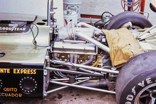
A view of the Smokey Yunick-built twin-turbo Chevrolet as it looked in 1973. (photo copyright Jim Edwards Collection, provided by Bill Ashby, used with permission)